Digitabulum r1 has a much improved interconnect strategy. This is a single digit.
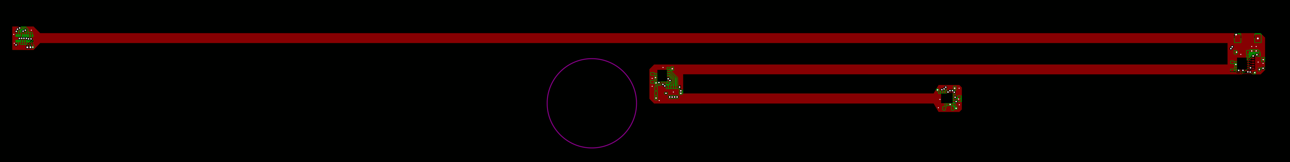
See that dark purple circle in the middle of the image? That's the footprint of a US dime.
Intent:
Stackup is 4-layers with (nearly) unbroken power planes on the outside layers. This is for inductance and EMI control.
The nodes are rigid FR-4. The long runs are unsupported polyimide flex.
There are no vias in the flexible regions.
No single signal experiences more than 2 vias. One at origin, and the other at terminus.
The metacarpals position has a different design, as it only needs to support a single IMU, but it uses the same connector. I took care to ensure that the digits and the metacarpals connections would not be mutually-confused by rotating the metacarpals connector by 90-degrees. Even if they are confused the mistake would not destroy anything.
Major changes:
- The LED was moved to the proximal phalanx. On r0, it was at the distal. It is also independently grounded and supplied to prevent noise from the PWM from translating into the power planes.
- No intradigit modularity. r0 had independently-replaceable sensor boards. This was helpful for debugging and testing things (such as loss-of-digits). But it dramatically increased bulk and cost, as well as made r0 intolerably fragile.
- This design uses the LSM9DS1 instead of the LSM9DS0. This part is smaller, lower-current, and has better internal organization that will allow cleaner filtering.
- Onboard IRQ aggregation. This allowed a savings of 9 conductors while retaining all IRQ signals.
Retained ideas:
- Strict copper keep-outs under the IMUs.
- Independent chip-select lines.
- Completely hand-routed. This was necessary to achieve the density while ensuring that important signals don't experience unnecessary vias, risky routes, or large differences in length.
- Digit-level modular. If a digit is damaged, it can be replaced by the end-user with no more than a screwdriver.
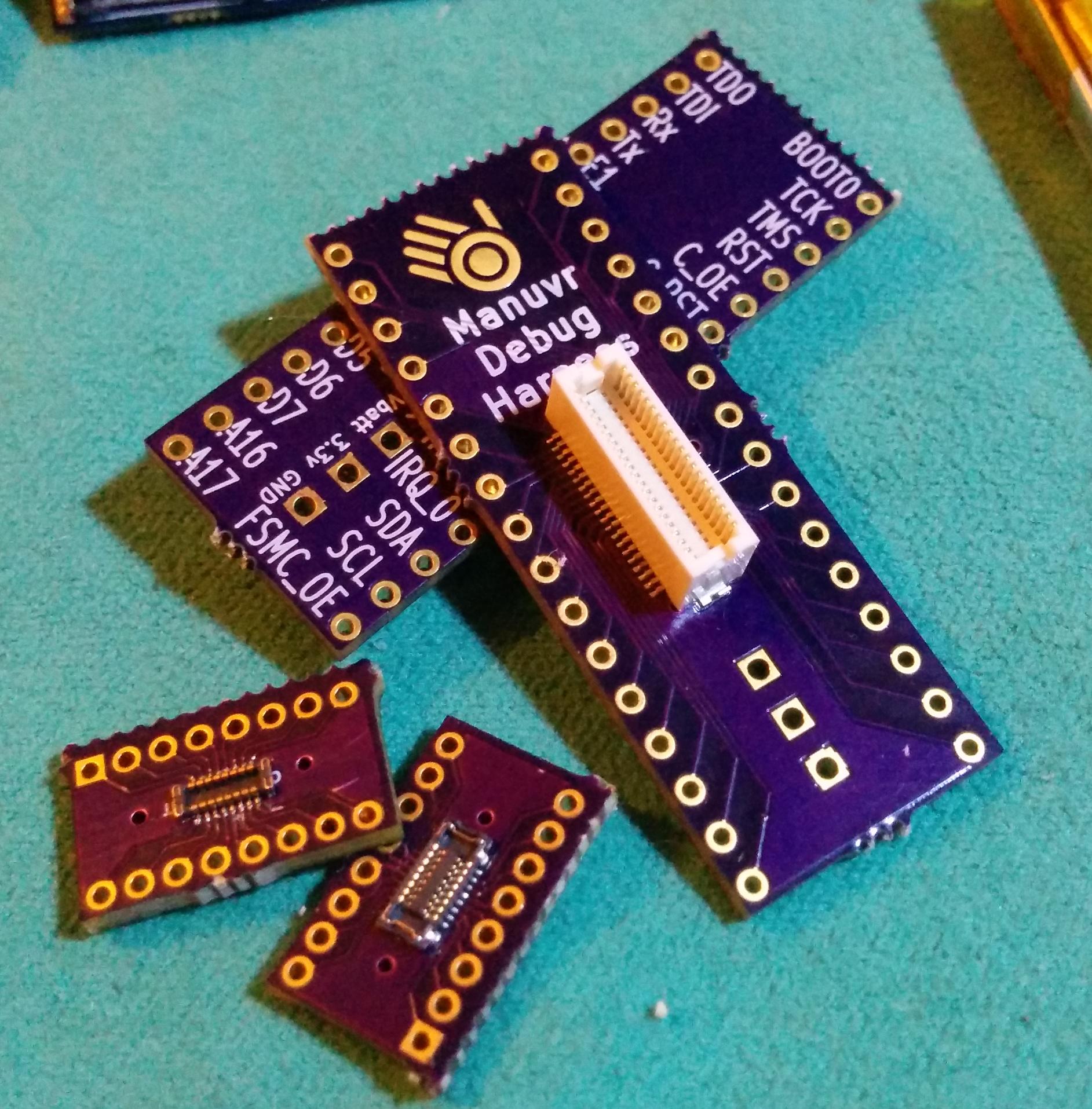
Pass-through harness
These are for the sake of development. The two small boards in the lower-left are an M/F pair of connectors back-to-back. This will allow the analysis of digit signals with and without the digit connected. CPLD hackers can contact us if they want their own. They are not silk-screened because of space constraints, and the connectors aren't keyed anyhow.
Timeline and next tasks
At this point, there will be some back-and-forth with the manufacturer. Once the ambiguities and kinks are ironed out (if any), manufacturing can proceed, and I will spend the next month coordinating the cutting of the casting mold.