Proof-of-concept unit
This was the glove and carrier-set for the proof-of-concept. Wearability has been one of the most serious concerns, and the source of the most surprising challenges throughout the project.
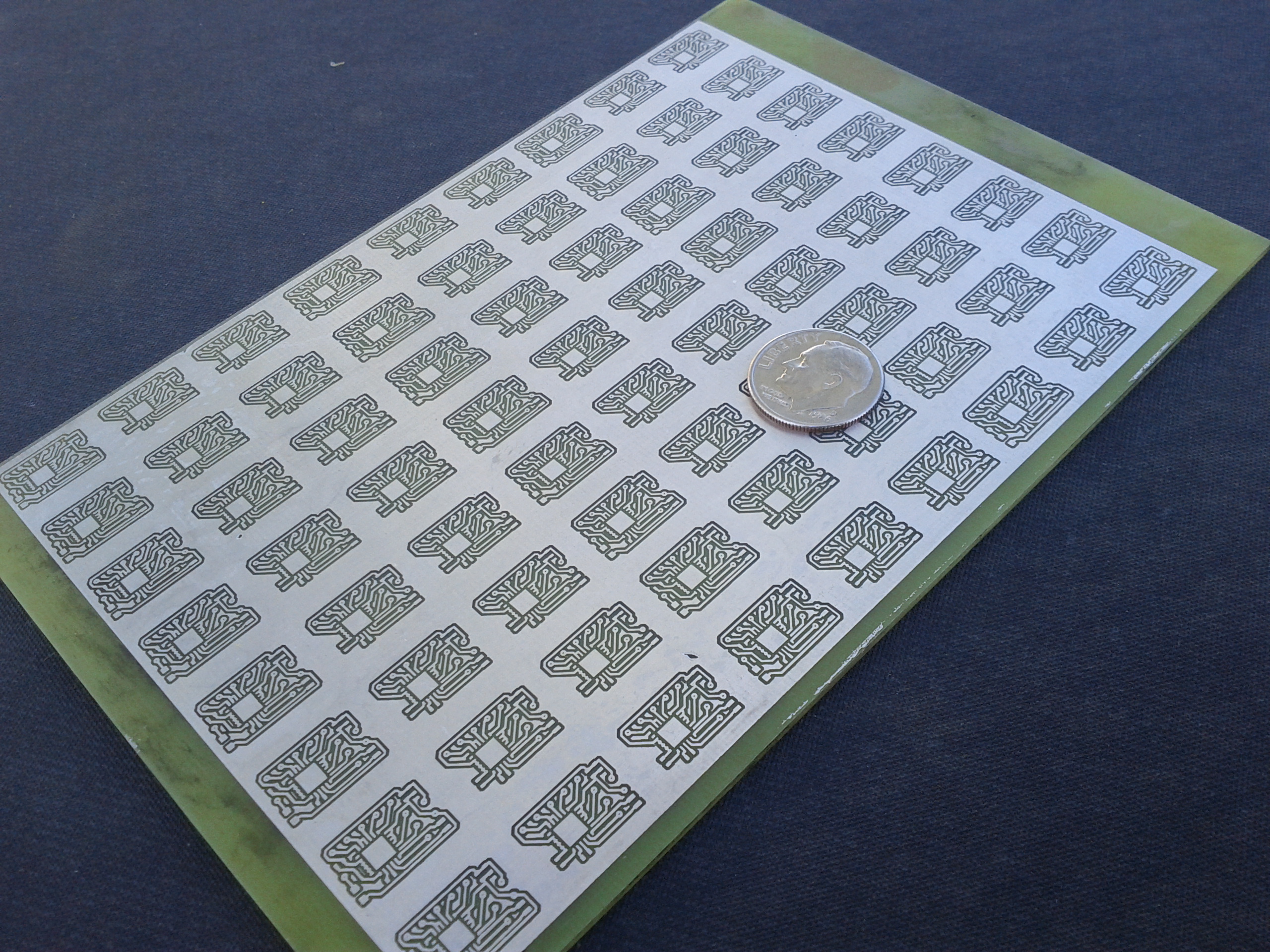
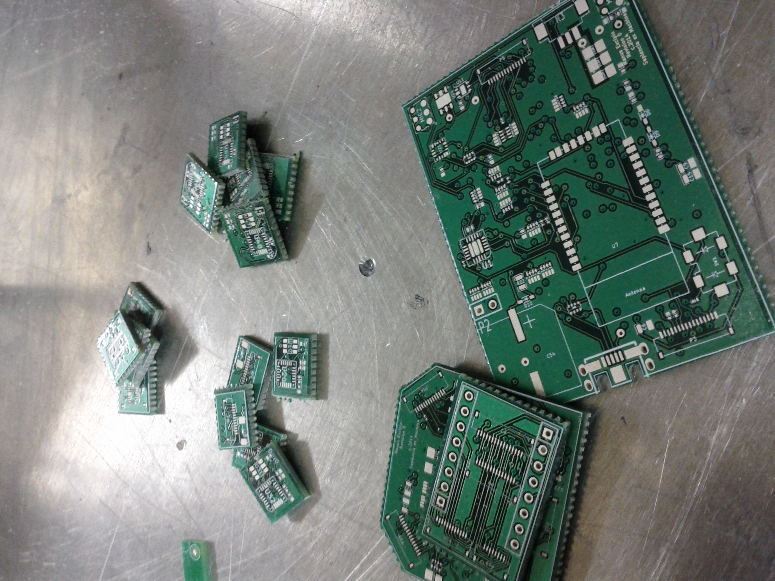
This is the original run of phalanx PCBs. I expected very high attrition rates, and I needed enough IMUs to build a full digit (at least). Cutting these apart and filing them down to size was a worse experience than you are probably imagining. I won't build something this way ever again.
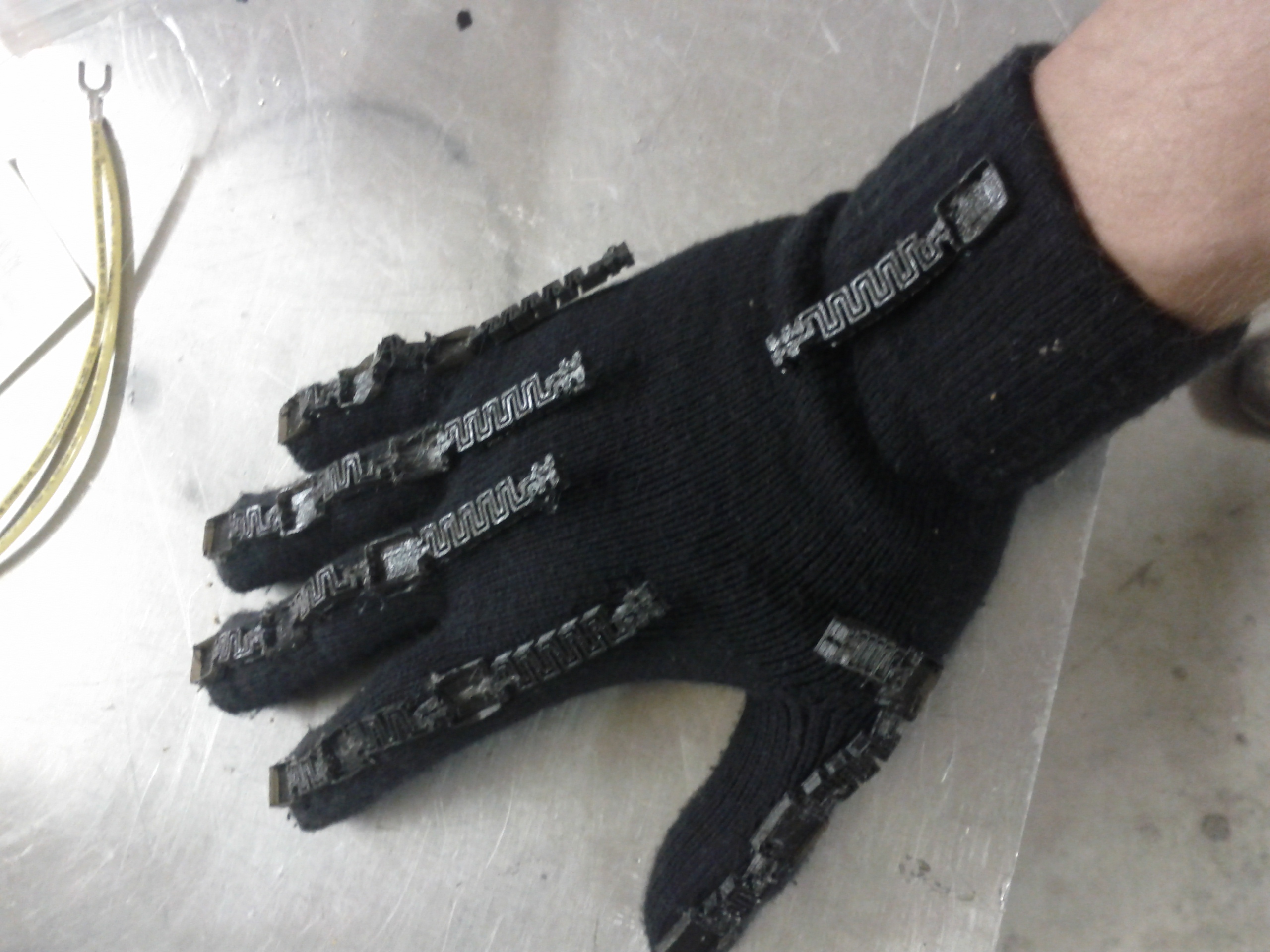
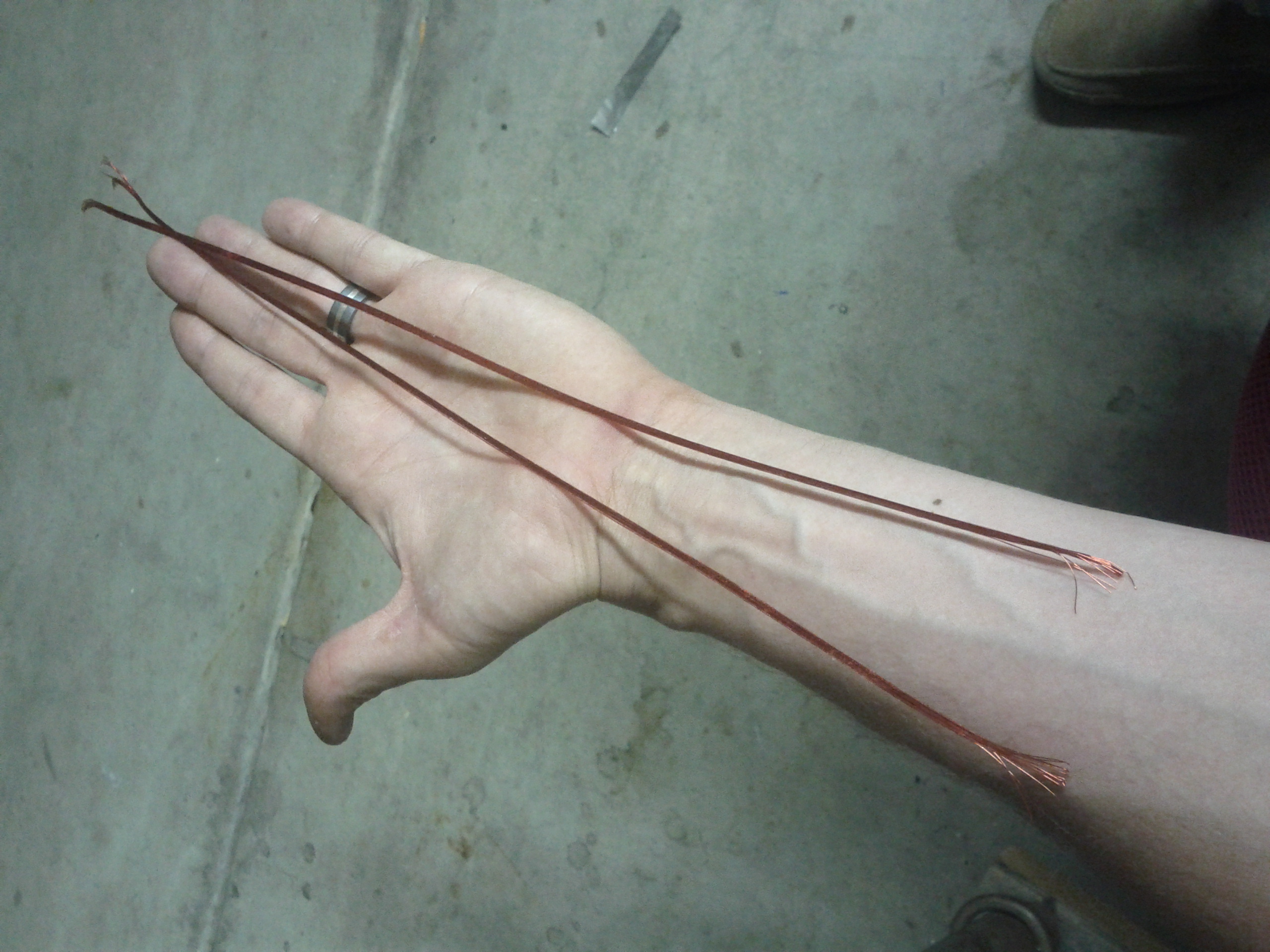
Wearability and interconnect are related problems in this case. In fact, interconnect accounted for ~30% of the BOM cost of r0. But for the POC, I didn't care if I could ever wash the glove or remove IMU boards for service or diagnosis. I cared more about flexibility and the capacity to build them in the garage. So my first interconnect strategy was a silicone-coated bundle of #32 magnet wire.
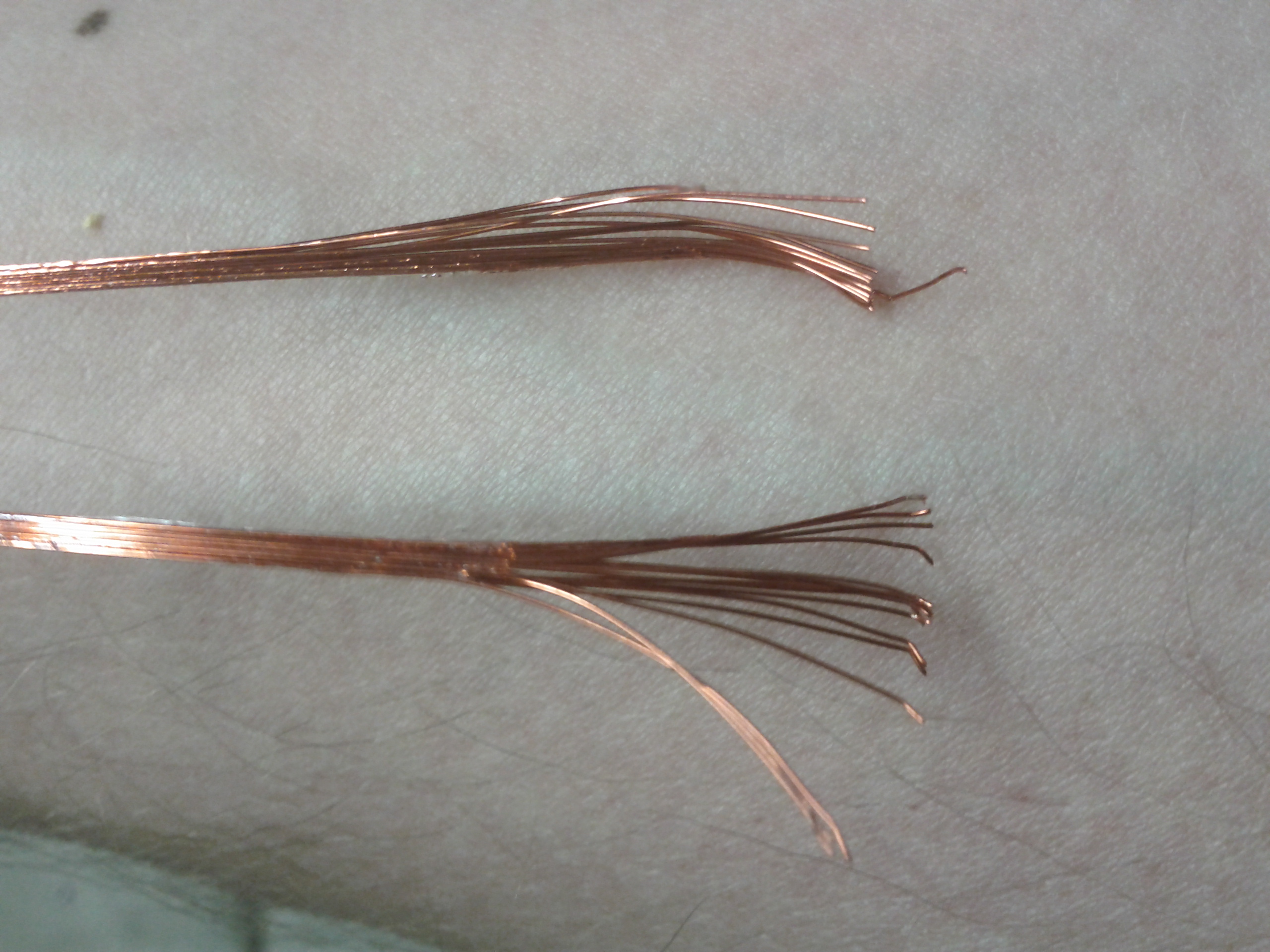
Close-up of the frayed end where I stopped the silicone coating. I won't build something this way ever again.
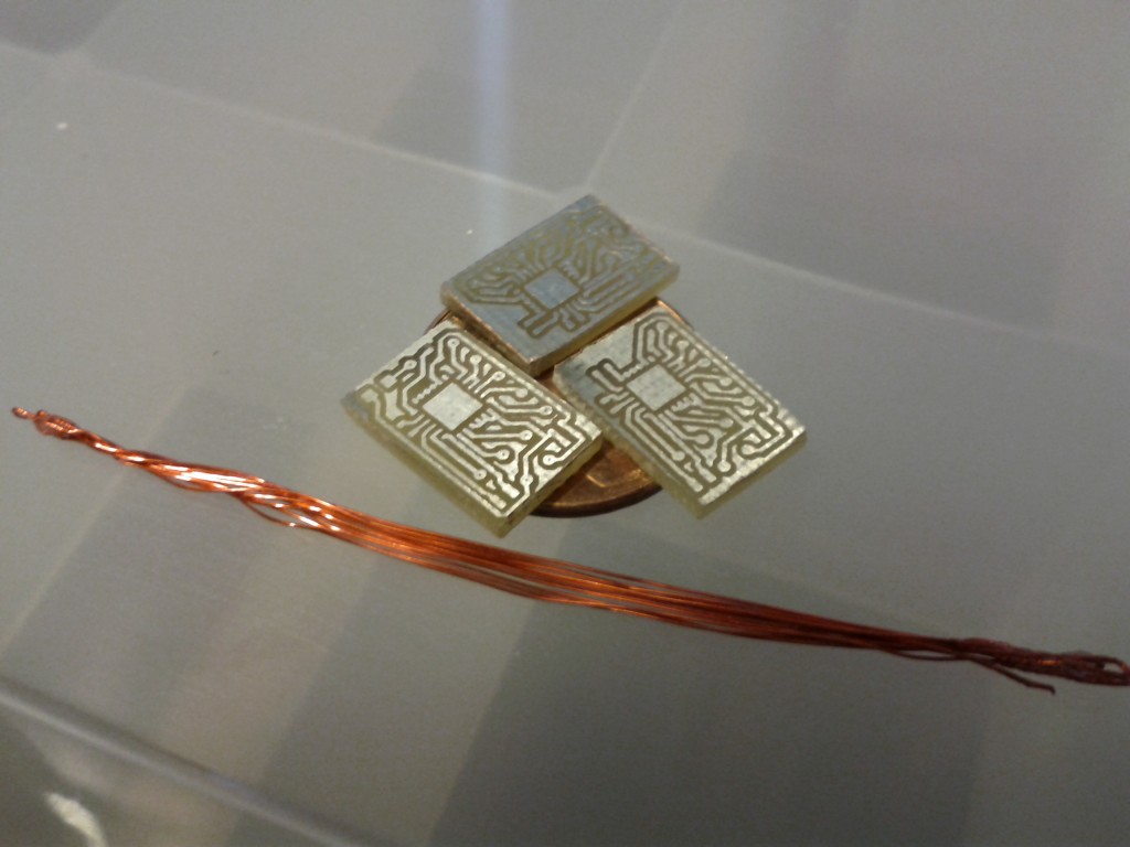
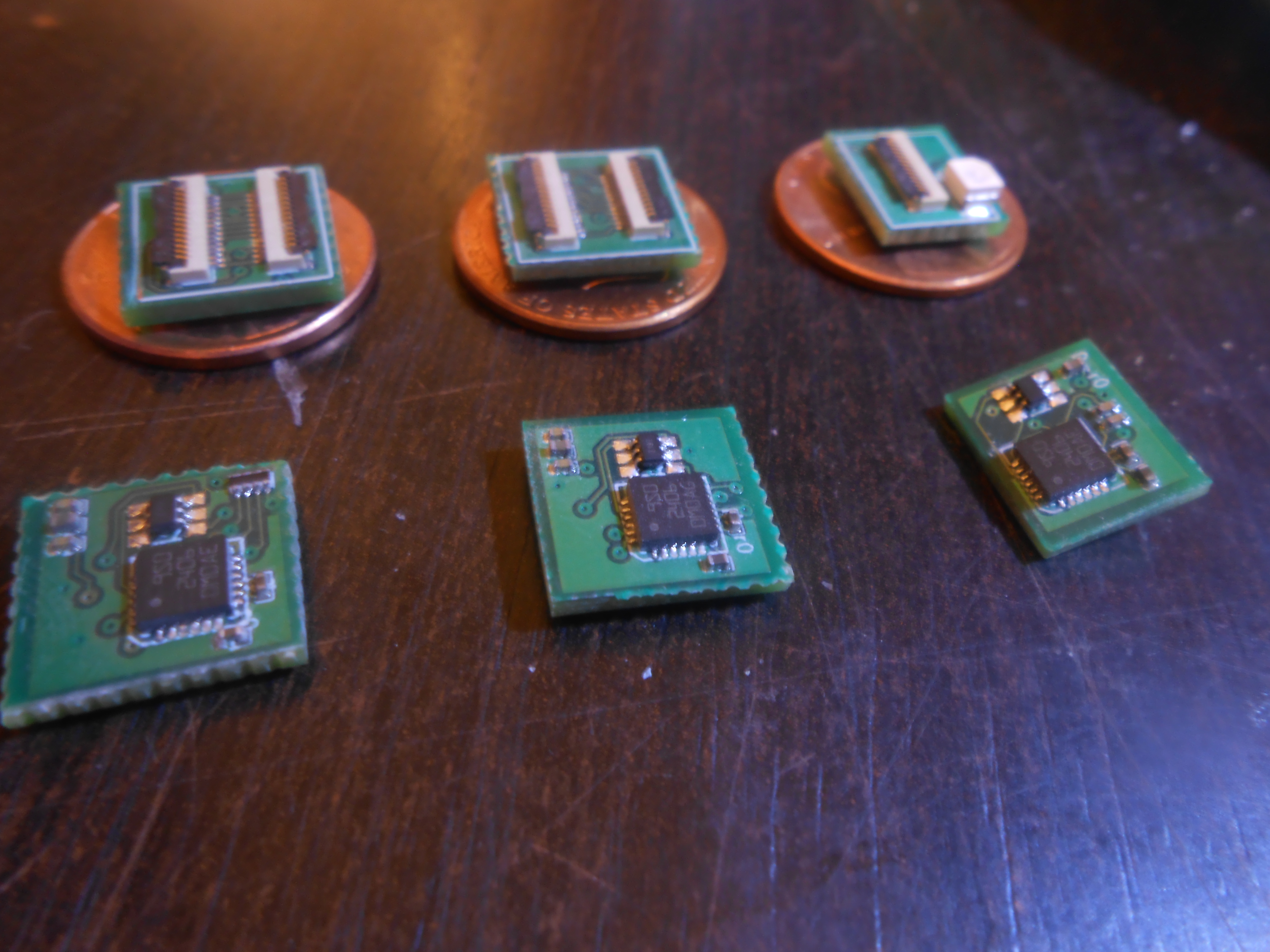
Here is one-digit worth of interconnect and viable blank PCBs after de-paneling. The PCBs are balanced on a penny to illustrate the size.
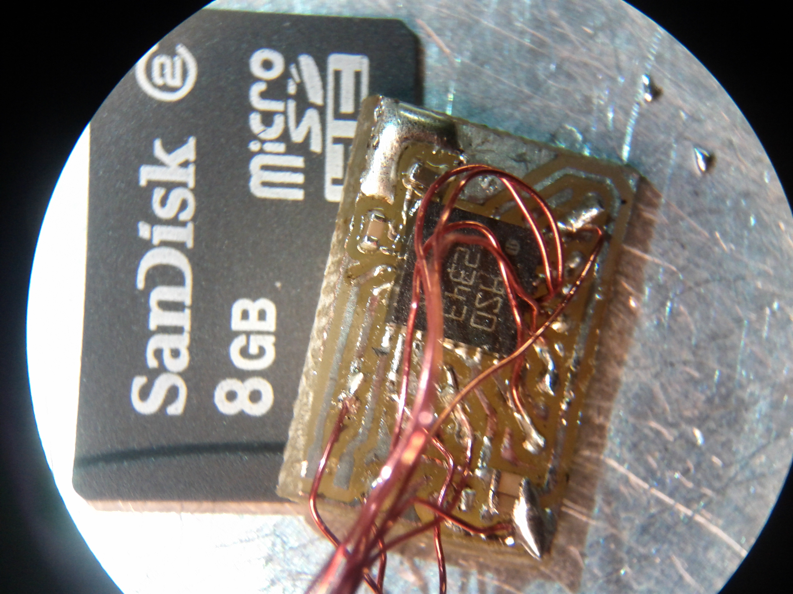
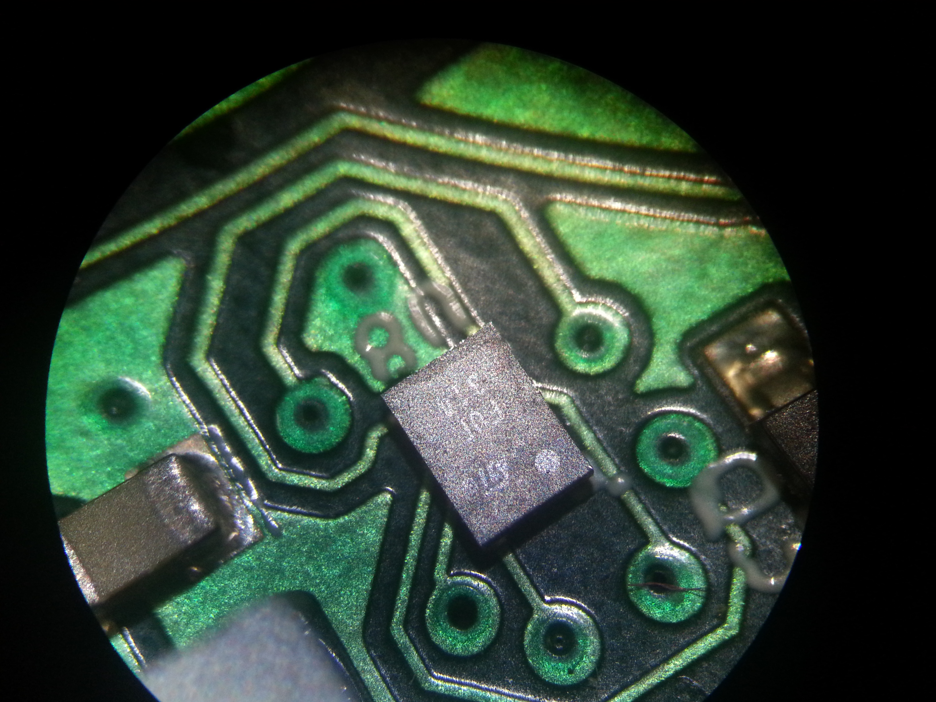
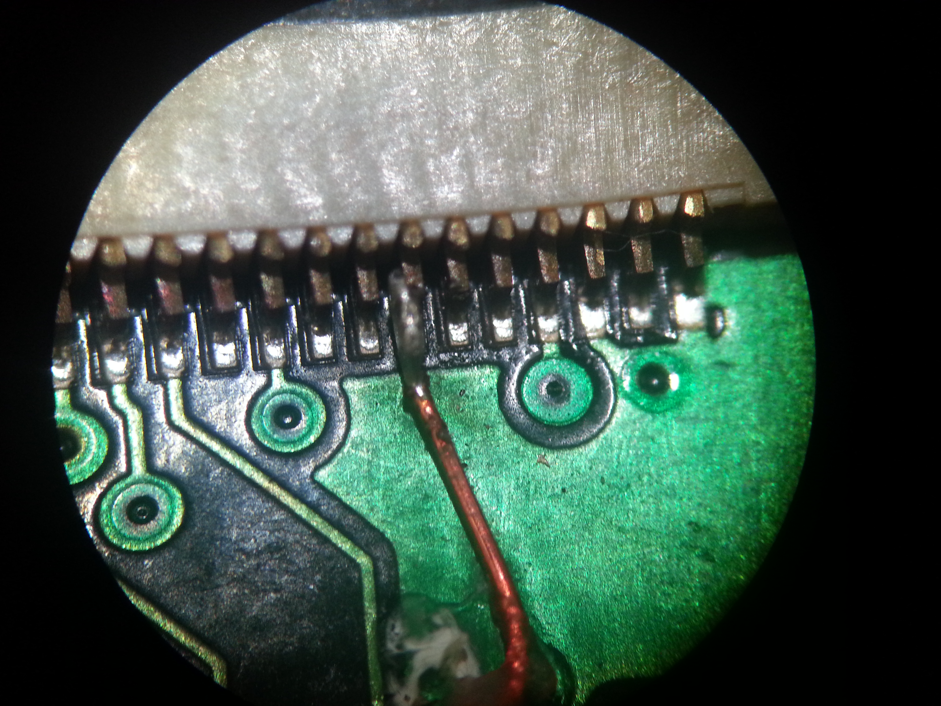
Here is a shot through the microscope of a finished phalanx PCB with interconnect attached. After these tested good, I epoxy-dipped them to prevent broken wires, water-damage, etc...

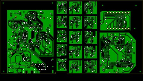
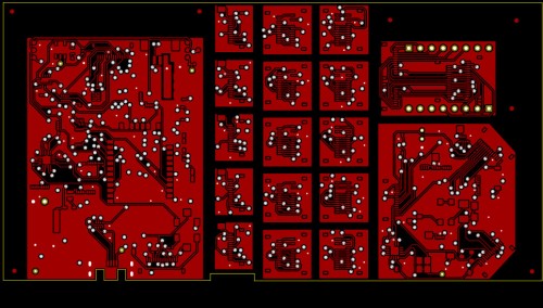
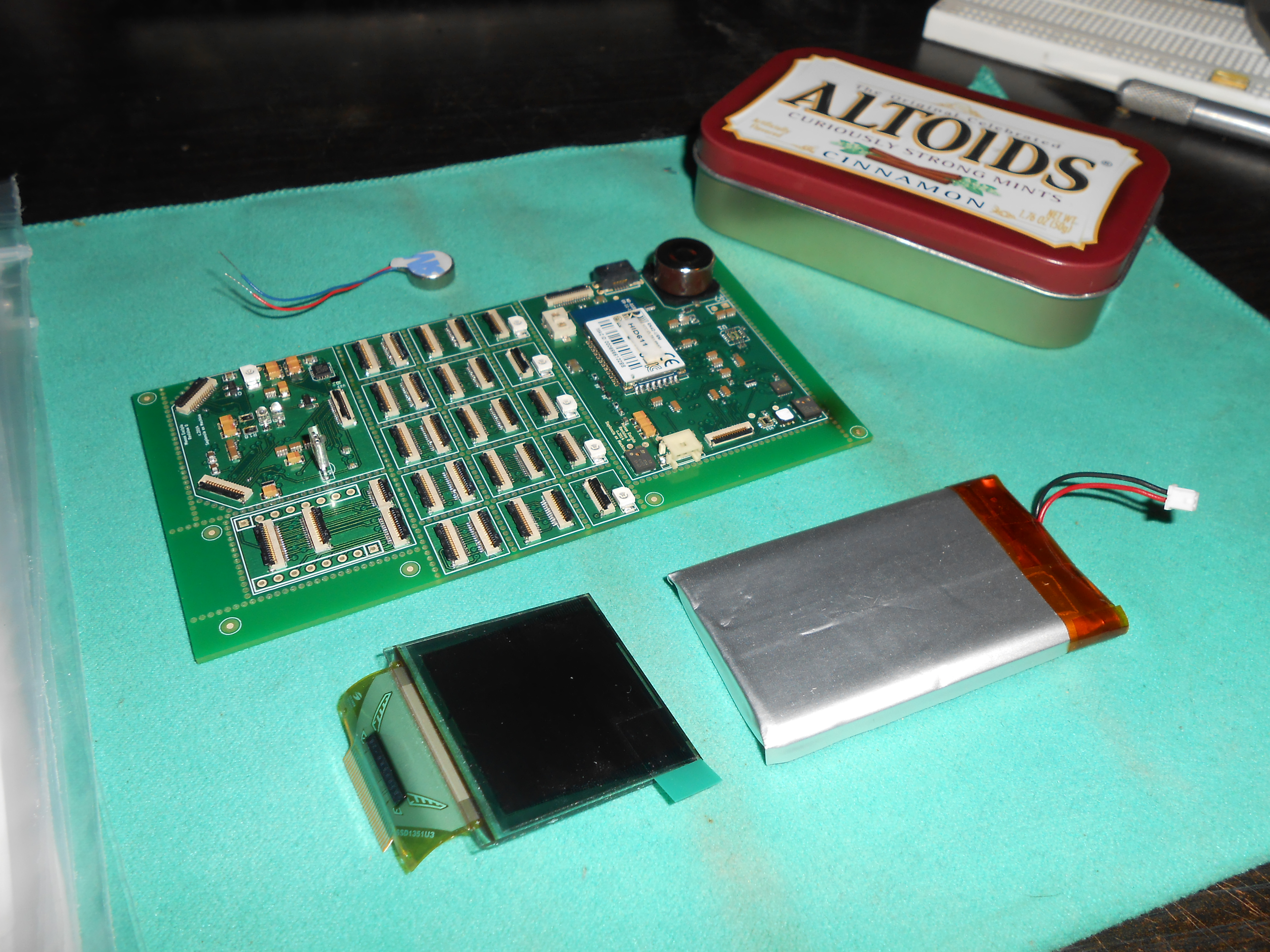
Digitabulum r0
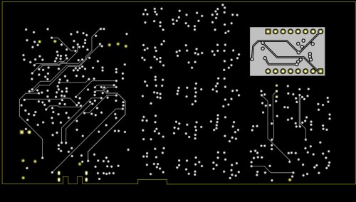
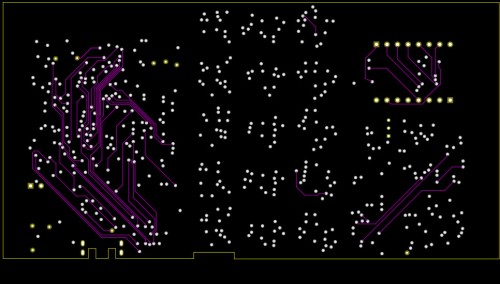
After building a single digit in the manner depicted above, and seeing that my bus design idea was viable, I set out to design r0. After reading a mountain of datasheets and drinking enough Red Bull to kill a horse, I arrived at this stack-up. The PCB set was 6-layers, so the power planes are excluded from this set, as they are largely uninteresting.
...and about $3100 after that, I had this gorgeous prototype delivered to my door (just the PCB, the rest of the hardware outlay was independently gathered):
Before I de-paneled the very expensive one-off with my hacksaw, I tried it on one of the unpopulated PCBs that the fabricator sent back with the assembled panel.
This process went smoothly, and the next day I cut apart the assembled PCB into its intended sub-units. Only at this point was I able to verify that r0 booted.
Here is the r0 PCB set (top and bottom) balanced on pennies. As you can see, the size grew somewhat compared to the POC. But the whole reason for this was to accomodate the connectors for the flex cables. These design problems have been solved for r1.
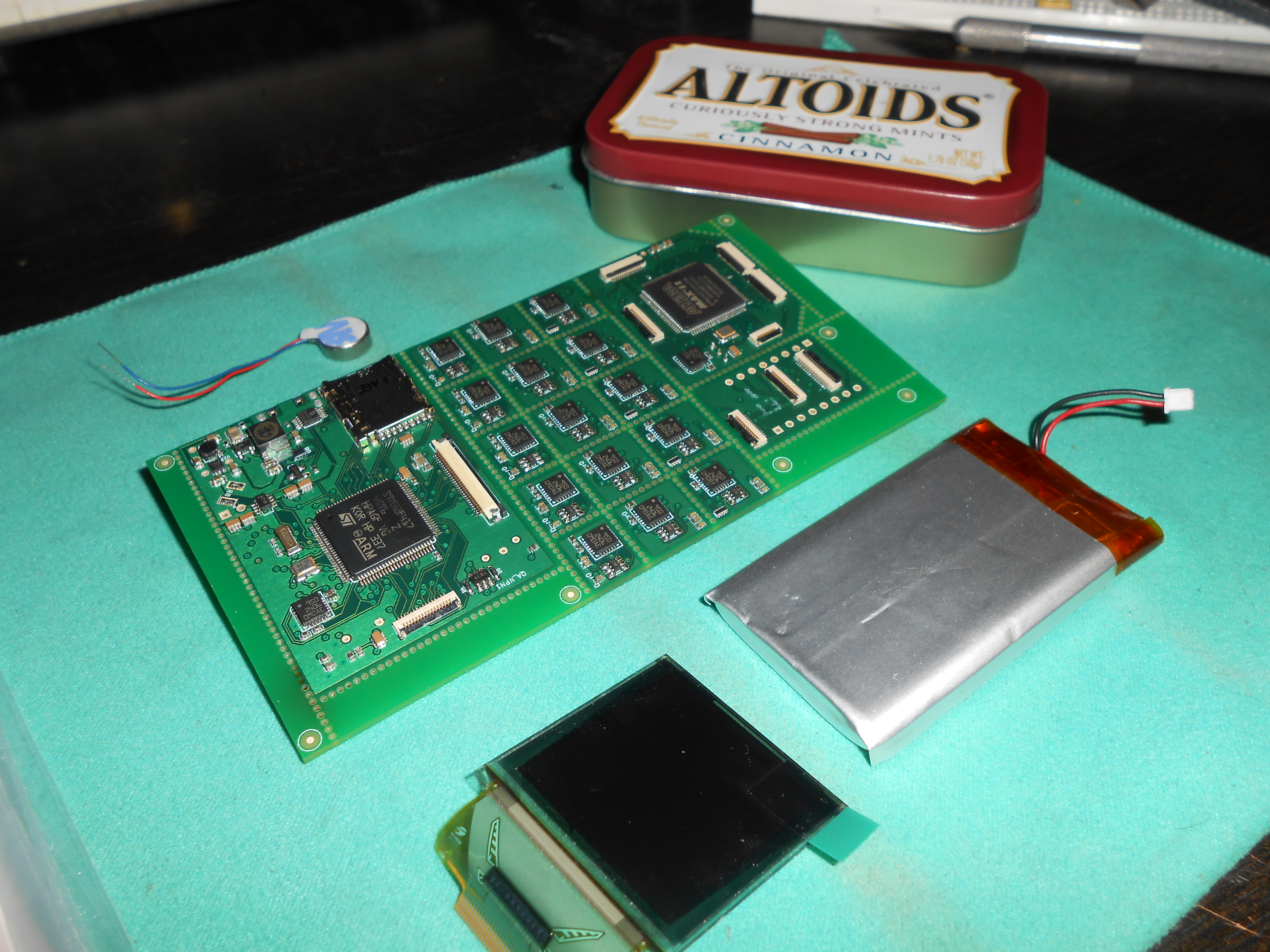
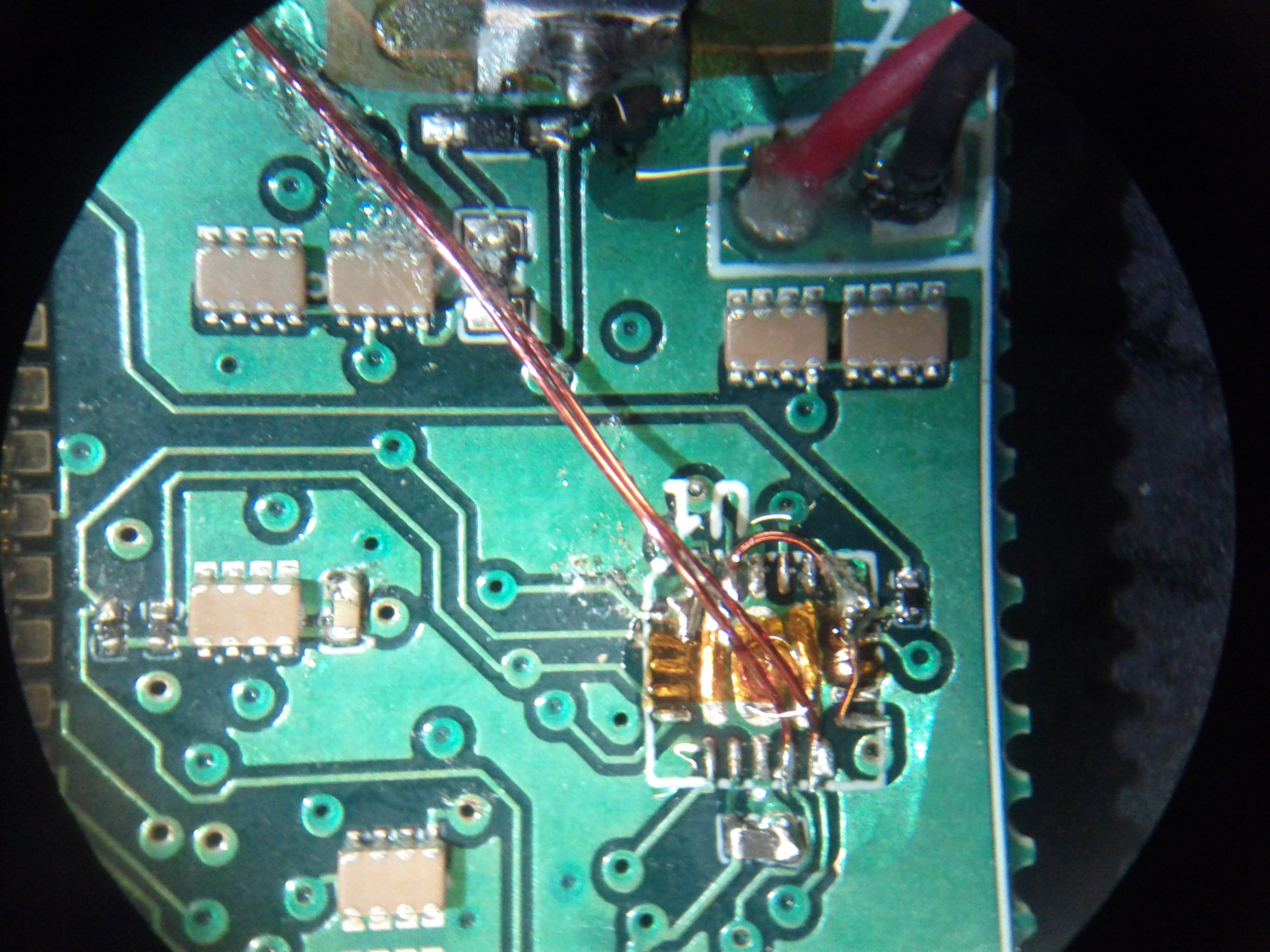
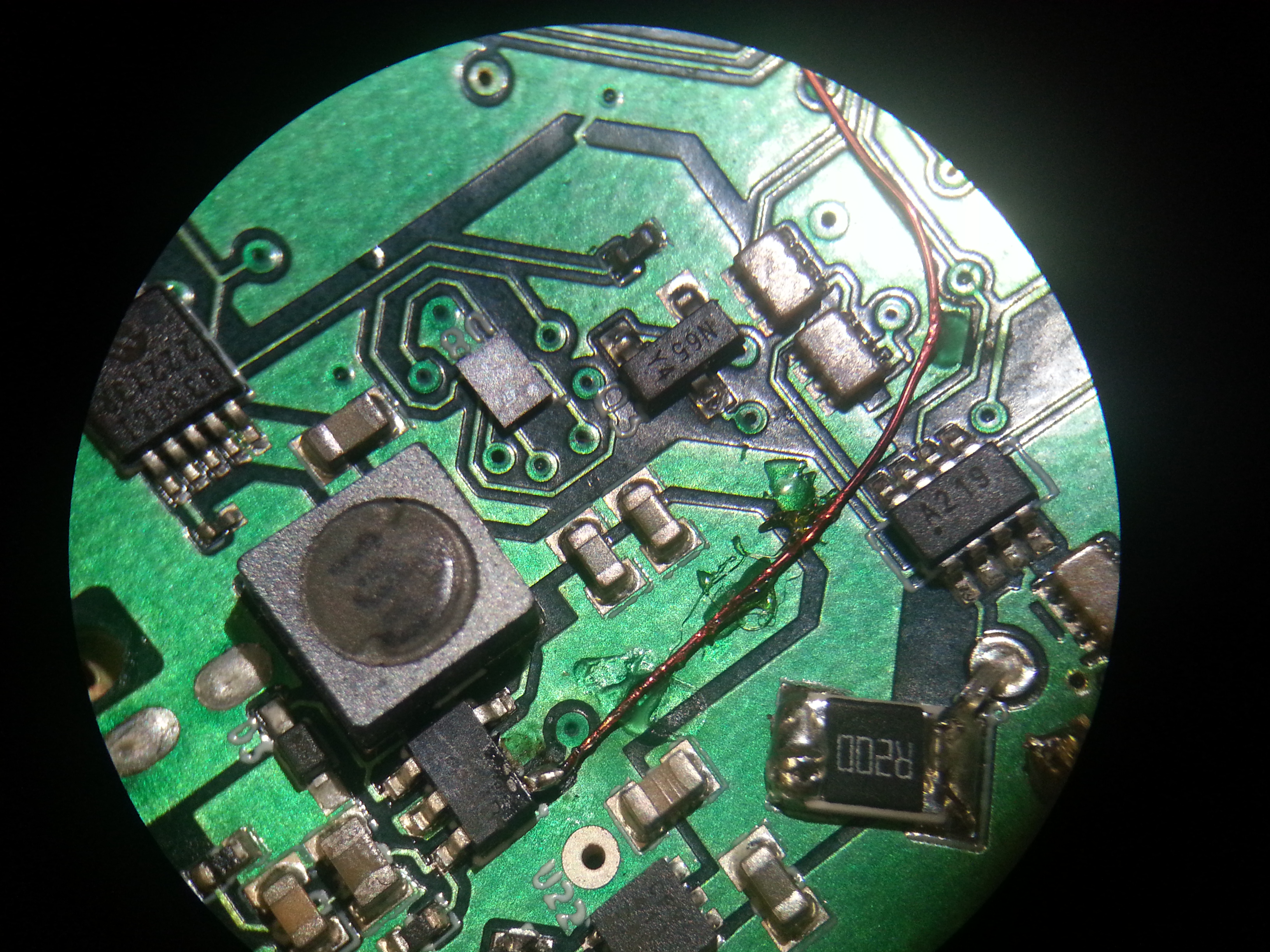
This was the smallest feature on the r0 PCB. This is the EMI-suppression chip that sits between the USB connector and the CPU, and helps prevent static discharges and other electrical violence from frying the CPU. There are 12 pads on this IC, and they are each 250 micrometers in diameter.
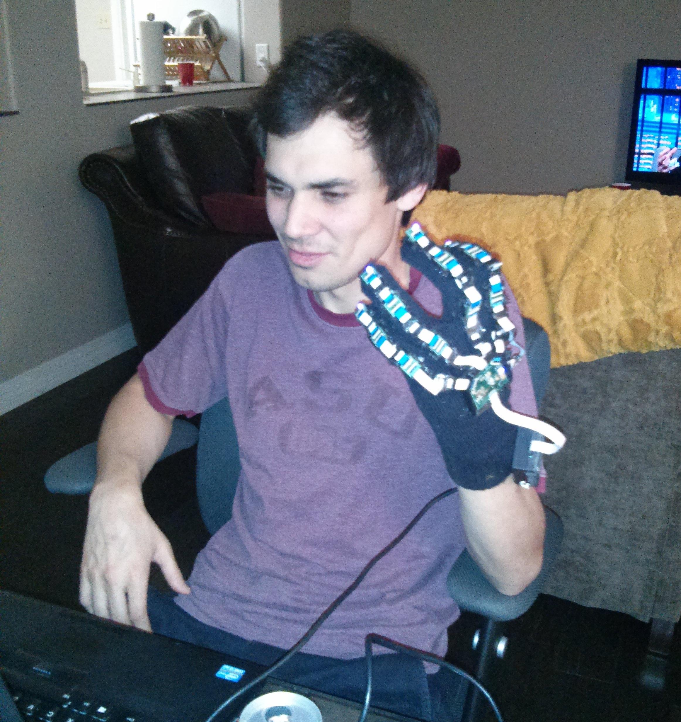
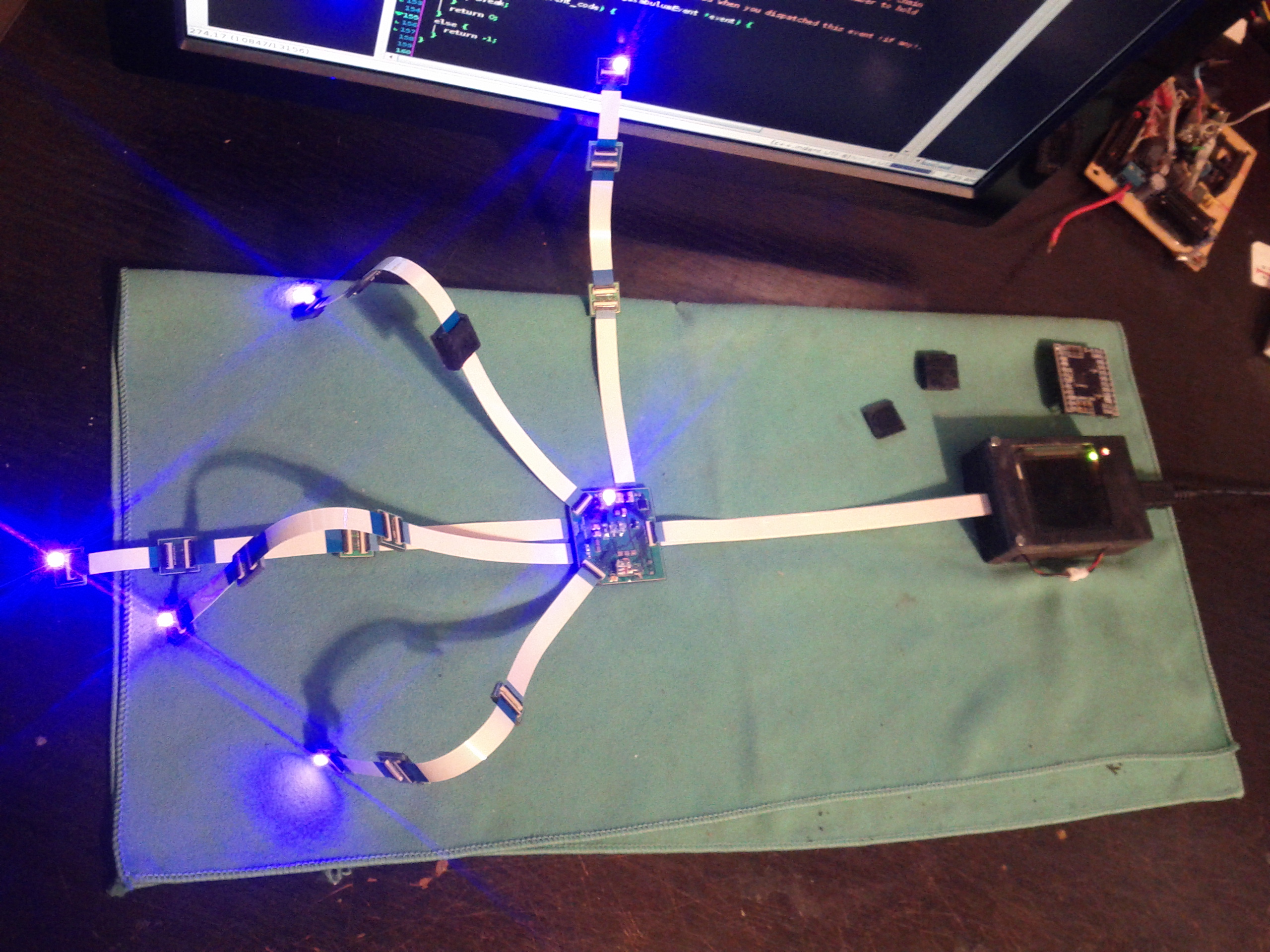
LED's lit up and under software control for the first time.
Corrected mistakes on r0
These were photos of various repairs that were made to r0.
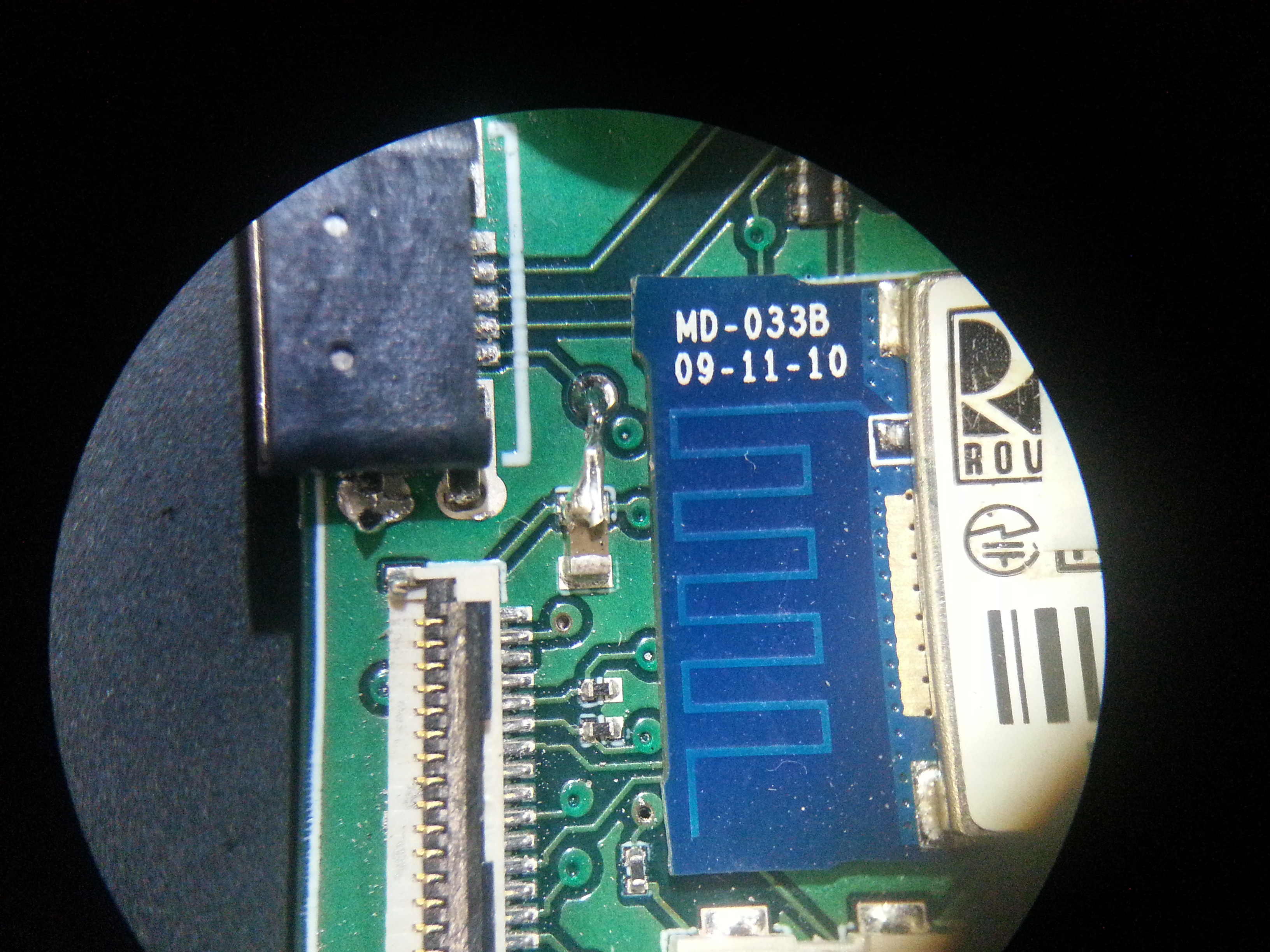
This was the most-serious mistake. I mis-spec'd the lands for the GPIO IC. They were 0.4mm pitch and I built the lands as if it were a 0.5mm part. There was no workable substitute, so I had to either sac or re-route signals.
One consequence of the U1 mis-place was that I had to re-route a regulator enable line (both ends of the wire depicted):
Fixing a net that I failed to join at a pavilion...
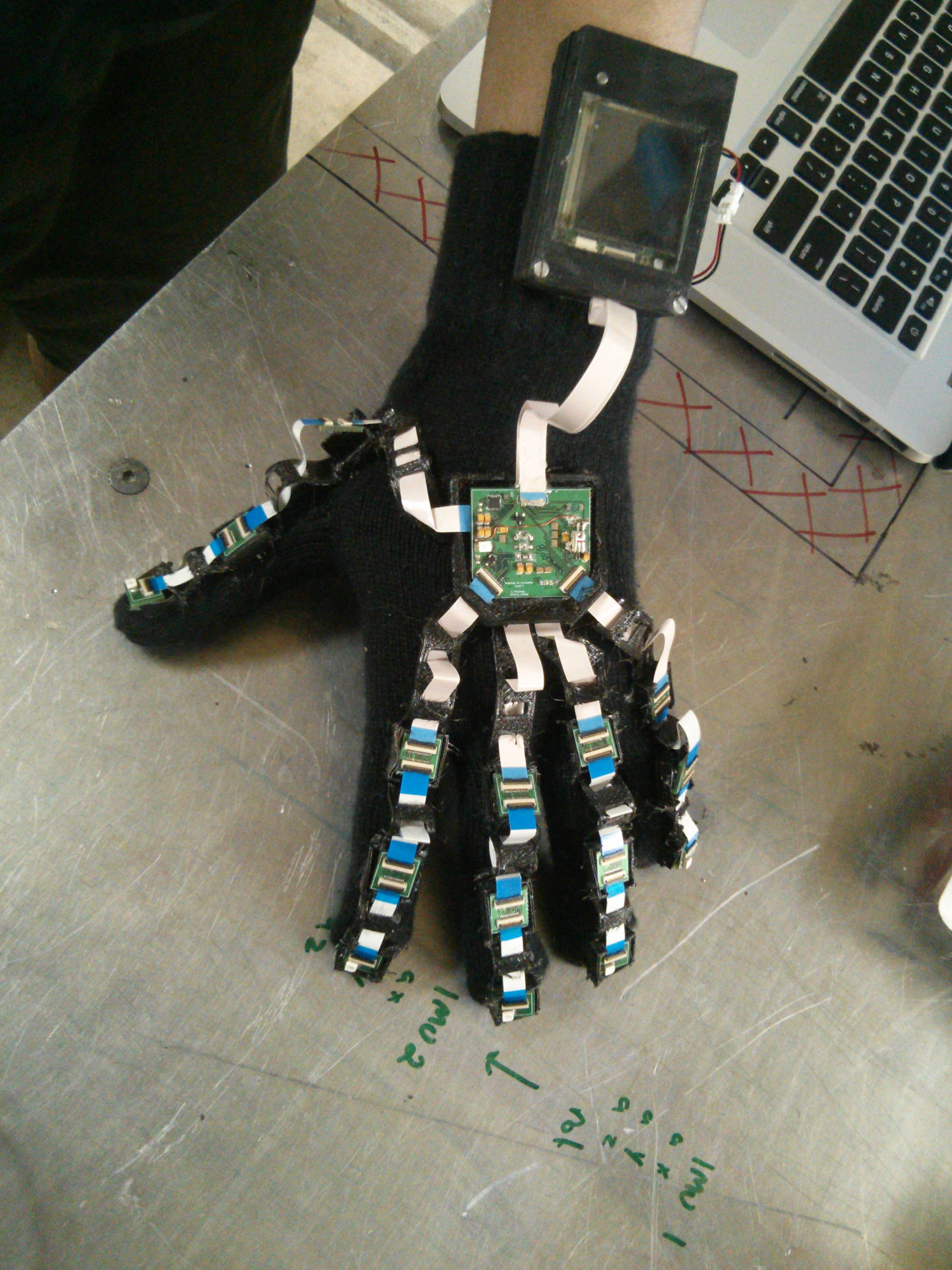
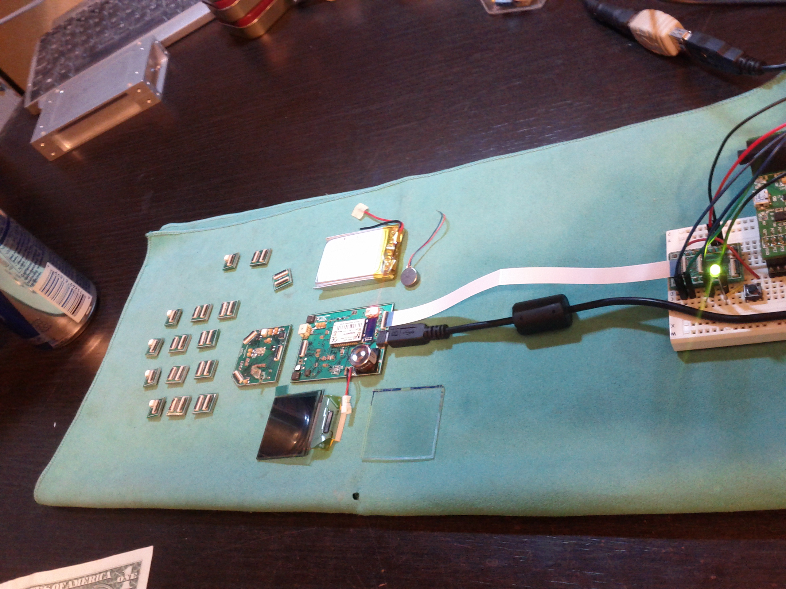
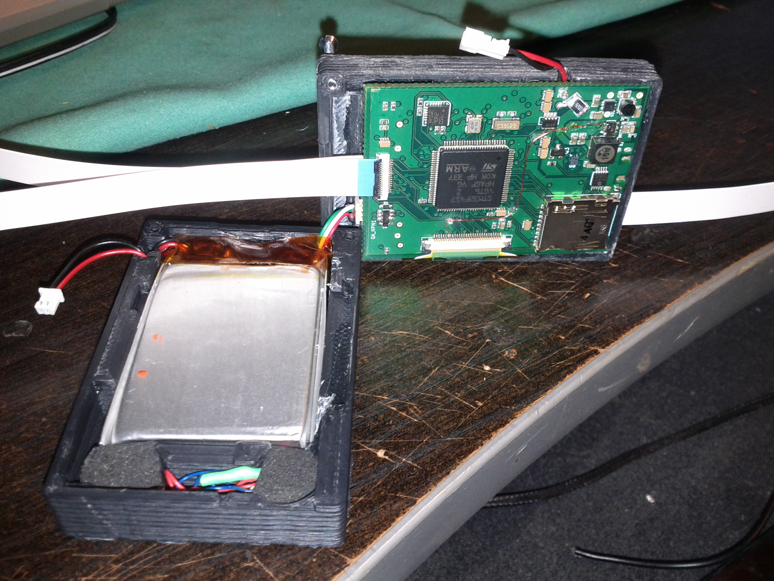
Mounting r0 onto a textile
A few days in Blender and I had done my 3D models of each part in r0...
...so that I could 3D-print the enclosure for the main unit, as well as the digit carriers...
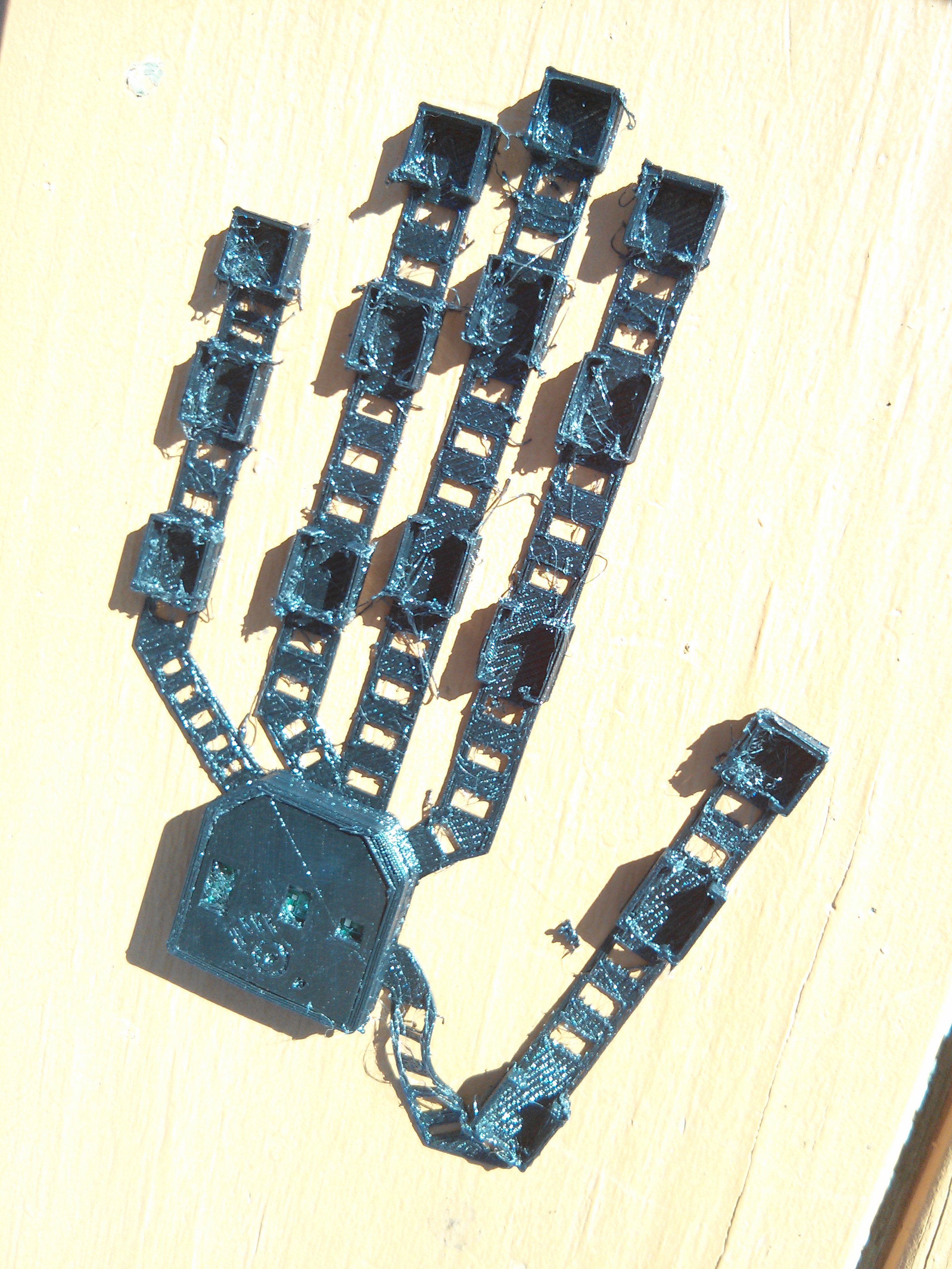
Present state: Wearable
Range-of-motion is un-impaired with the exception that my fist can't be as tight, owing to the extra material surrounding it. The FlexPLA digit carriers don't put up a noticeable resistance to normal hand usage.
The worst thing about the wearability of r0 is related to the flex interconnects. Without anchoring, they have a tendency to slip out of their connectors. These problems have been addressed in r1. Details, renders, and pictures of the new r1 digit are forth-coming.